Classic DIY electronics resources
Posted this a while back but figured it’s worth sharing again. These are some classic electronics books with great info relating specifically to audio circuits.
Handmade Electronic Music by Nicholas Collins - Excellent resource if you are just starting out!!
Engineer’s Mini Notebooks on Op Amps by Forrest Mims III - Also great for beginners with slightly less hand holding
CMOS Cookbook by Don Lancaster - Upper beginner to intermediate
The Art of Electronics by Horowitz and Hill - When you are ready to start getting more serious
Small Signal Audio Design by Douglas Self - Solidly intermediate but a great reference and explains the “why’s” nicely
A deeper dive into the Quad Comparator
We’ve been deep into classes mode and have been neglecting the hardware side of things but recently had a little free time to put together a video about using the Quad Comparator to process audio. This deeper dive into the Quad Comparator has been long overdue so we are happy to put it out into the world (complete with a goofy click-bait style thumbnail).
We don’t have a ton of these in stock, and have been building a lot less modules in general lately, so if you’re interested we suggest snatching one up while you can.
Please feel free to leave a comment or contact us with any questions.
Voltage, reference points, and window comparators
As I reflect on questions that have come up in the Creative Electronics for All classes and simultaneously consider the best way to talk about what the Quad Comparator does, I have found myself spending a good amount of time chewing on the concept of voltage.
I often think about a water tank to conceptualize what voltage is. I can see the iconic NYC water tanks sitting on top of their buildings and think about their potential energy. I imagine connecting a tiny hose to it and mischievously spraying water on the street below and also consider the full contents dropping down on me as one giant, consuming mass of water.
A voltage is potential energy. It is broadly speaking a pressure from a power source that pushes electrons through a circuit, enabling work to be done. The batteries we use in CEFA classes are 9V, the voltage coming from household outlets is 120V, and regardless of how much you know about the science it is likely clear that one has more potential than the other.
In order to measure voltage we need a reference point. Often this is some kind of “ground” or a return terminal (the place where the electrons theoretically end up). It can be literally the earth ground (everything “theoretically ends up” there) or the chassis of a piece of equipment or vehicle (chassis ground) or a reference/return point in a circuit (signal ground). When we measure how much voltage a battery has we use its opposite terminal as a reference - that’s where the electrons end up and we often use it as signal ground.

I often see these used interchangeably (particularly signal and earth), but it’s good to know the difference when looking at a schematic.
A comparator is a circuit that compares an incoming signal to a reference voltage. The comparator has two inputs (signal and reference) and one output. It can be configured so that the output is high when the input signal is greater than the reference voltage or alternatively output high when signal is less than reference.

Purple area highlights where signal is above the reference point. The wave is alternating between 0V and 5V, and while we didn’t specify where the reference point is, we can see that the red line is somewhere above halfway (call it 3V?).

In this case the purple area highlights where signal is below the reference point.
A window comparator combines both of these options, so the output is high when the input signal is between two reference points.

Output is “activated” (high level out) when wave passes between the two reference points, low when it is above the high reference or below the low reference.
The Quad Comparator module consists of four window comparators with manual control of high and low reference voltage for each. Additionally the inputs are default connected together, so all four window comparators can be used on one incoming signal.

The four window comparators each have controls to manually set high and low reference voltage.

The inputs are normalled together so that the four window comparators can work together on one incoming signal or work independently on separate signals.
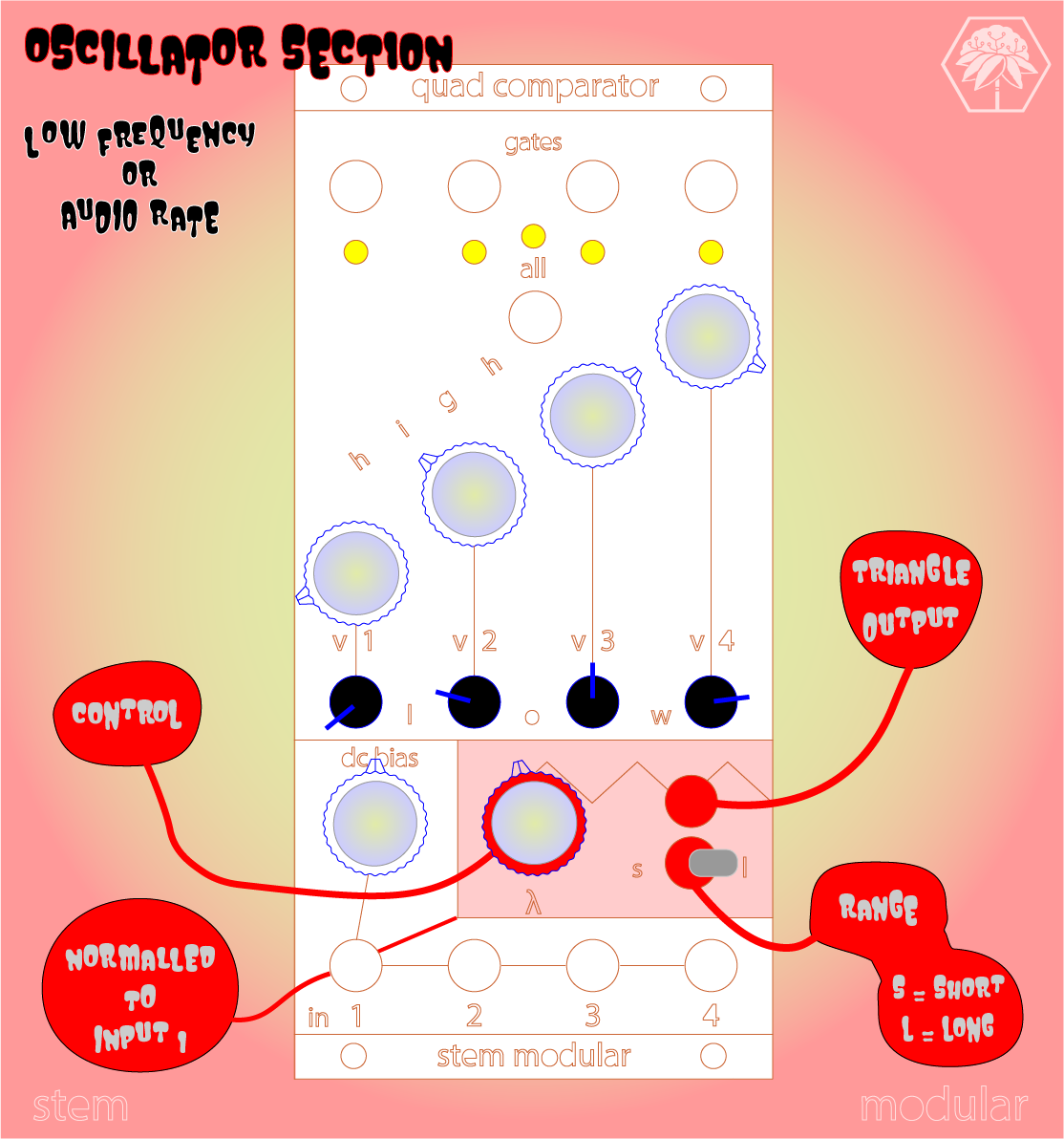
An internal oscillator is normalled to input 1 and allows for the module to be used without any external signals. DC bias shifts the incoming signal higher or lower.
The concept may feel more convoluted than a typical sequencer at first, but it is actually pretty straightforward. Because of its flexibility it can be used to create sequences, pulsewidth audio, distortion, and more depending on how it is configured.
If you’ve made it this far and are interested in learning more, look into our classes (we’ll be posting some new ones soon). Eventually we will be making some window comparator diy projects available, but no idea when at this point. If you have any voltage wisdom to share, please feel free to leave a kind comment.
DIY eurorack drums with a Teensy
Recently I wanted to add some drums to my systems, specifically taking advantage of the gate outputs of the Quad Comparator to sequence some beats. I had a Teensy 3.6 and knew there was some example code that uses it to play drum samples triggered by a push button. The beauty of modular is that we can replace a button push or knob turn with control voltage, and doing so with the Teensy turned out to be pretty straightforward.

The official Teensy audio examples use tactile buttons to trigger events, and in the “sample player” example it sets the Teensy inputs to a “high” (in this case 3.3V) voltage level using an internal pull up resistor, and when the button is pressed that voltage goes “low” (GND or 0V). I’ve included an image of the main loop below where you can see “fallingEdge” being used to determine when a sample should be played. In the case of the “button0.fallingEdge()” that I highlighted, that means when the Teensy sees button0’s pin go from high to low “button0.fallingEdge()” will be TRUE and it will play “AudioSampleSnare”.

In a modular system we can use triggers or gates to create the same edge that would result from a button press. To do this I used an NPN transistor, which is a component that can be used like a voltage controlled switch. This will allow us to keep the signal to the Teensy at a value that is safe for it, and require no change to the code, since we can easily convert the rising edge of a gate to the falling edge expected by the code.
To swap the buttons out (and make for as little coding as possible) we want a circuit that pulls inputs to ground when gate is active. We can set an NPN transistor up so that 3.3V is at the collector and GND is at the emitter, so when the transistor is in saturation mode (acting like a short circuit) the Teensy pin will be pulled from 3.3V to GND (0V) making a “fallingEdge” that our code will recognize and do something with (trigger drum sound). Schematic for one gate to Teensy conversion is shown below.

What I was reminded of through internet searching/double-checking/self-doubting (ultimately from this ModWiggler thread) is that in addition to a simple transistor switch circuit I should also be careful about reverse voltage between the base and emitter of the transistor. This can destroy a transistor and a simple safety measure is to place a diode between the emitter and base (as seen in image above).
Now there are some way fancier ways to do this, but I was (and often am) looking for a quick way to get an idea up and running, and it doesn’t get much more straightforward than this. A more detailed explanation with modular example is in the works, but for now there’s this IG video and this TikTok. Feel free to comment any questions or ideas, but please be kind.
A brief overview of frequency modulation
Fresh video! We look into frequency modulation - a technology used in telecommunications, radio broadcasting, signal processing, and computing.
Patching is Programming
Recently I’ve been revisiting the basics of computer programming, and of course my brain immediately saw connections to modular synthesizers. Early analog computers are closely related to modular synthesizers - no mouse or keyboard, mostly just patch cables, knobs, and switches. So while the subject matter we cover with STEM Modular is on the surface about electricity and sound, we are simultaneously introducing the basic structure of coding. Consider three of the core concepts behind computer programming - variables, functions, and boolean logic.

Some old school analog computer situation
Warning! - What follows is EXTREMELY simplified!
If you haven’t come across variables, they are a placeholder for information that (you guessed it) varies. In mathematics we usually first come across variables in trigonometry or geometry, where we calculate shapes of different sizes by plugging in for instance different r (radius) values into an equation. In computer code we also use variables widely and to perform many different tasks including the size of shapes.
Without going too deep (and in the interest of simplification) a function is a piece of code that takes a variable and does something with it. For instance, a function could take numbers for width and height and draw a rectangle with those dimensions. Functions can also take a variable and output a certain frequency of sound on your computer speakers (sound familiar?). They are quite literally little modules of code that efficiently make your phone or computer do things.
A Boolean data type is a kind of variable, but rather than a number it has only two values, true or false. A boolean is like an on/off switch in computer code. Some functions use this data to make decisions.
In a modular synthesizer control voltage is the variable, and modules are functions. Modules that are voltage controlled take a control voltage input and do something based on that value (going back to the shapes analogy - the frequency and amplitude of a square wave are actually it's width and height). Some modules (like an envelope) take particular on/off values that we call gates, which are the analog version of a boolean.
So essentially when we are creating a patch we are doing an archaic version of programming.
Swimousine demo
Thomas from Swimousine stopped by the workshop and we filmed a short demo. It's a nice intro for folks new to the modular world.
The oscilloscope that everyone asked me about at Knobcon
So, a lot of people asked about the little oscilloscope that is in the 84hp Wave Station (see video in the previous post). While there will likely be a day where we develop a visualization tool of our own, this is not something that we made. Many educators really want to have a scope of some kind, and we found the cheapest, easiest way to get one in the system was to use this JYETech mini oscilloscope. You can find them as a kit or fully assembled for pretty cheap. We modified it to be powered by a Eurorack power bus, and swapped the BNC input for a 3.5mm jack.
Waveform magazine has done a similar modification that is a great option if you don’t want to dig in so deep (or if you are still building up your soldering/circuit modding skills). The point to be made here is that we are not responsible for you destroying your mini-scope (we have destroyed one ourselves in the process), but provide this information if it might make the job easier for folks who feel comfortable with this sort of thing. Below you will find some basic information and accompanying images, as well as a link to a file you can use to laser cut a front panel.
There are buttons that we haven’t bothered to pull up to the panel. We feel it’s just as easy to poke through, and generally this is a peripheral module that is not meant to be a major focus of the Wave Station (yet here we are). Again, Waveform’s DIY kit is a better option if you want the panel buttons. Feel free to comment with any questions and we’ll try to help as much as we can.

Le scope

Power connector. Shifted so red stripe hits ground pins and power comes from 5V. I use the excess clipped wiring elsewhere in the workshop.

5V goes to Vin and Ground goes to GND. Audio wiring to where the BNC would normally go should be pretty straight-forward if you’ve made it this far.
The easiest way to provide a download seems to be adding it to the shop. So it’s a little convoluted but free to download nonetheless.
Knobcon 2021

I had a blast at Knobcon! I met so many lovely people, and got to meet in-person with a bunch of folks that had become virtual friends over the past year. Thanks to JAde Wii for capturing the STEM Modular table setup.
Making the modular experience digestible for new users
We’ve got some fresh videos up on our YouTube Channel and will be posting some more introductory patches in the coming weeks. Modular synthesis can be intimidating at first, but a few simple patches can spark a multitude of ideas. We want anyone to be able to start playing with frequency, amplitude, and control voltages because we believe that it’s an empowering experience. Subscribe to our channel to stay up to date and let us know if there’s any concepts you’d like to see covered.
New panel variation
New panels alert! 🖤 We have added a black birch variation of our modules. Still striving to be as sustainable as possible and honestly the burnt wood text/lines against black finish is 👌. Bamboo is not going anywhere, but now you can choose the dark side.
⬛🎍🗽🎋🎛️⚫


December purchases support FeM Synth Lab (and 10% off for you!)
20% of purchases made in December will go to support FeM Synth Lab!
AND use the code “STEM2020” at check out to save 10% on your module purchases until January 3rd!

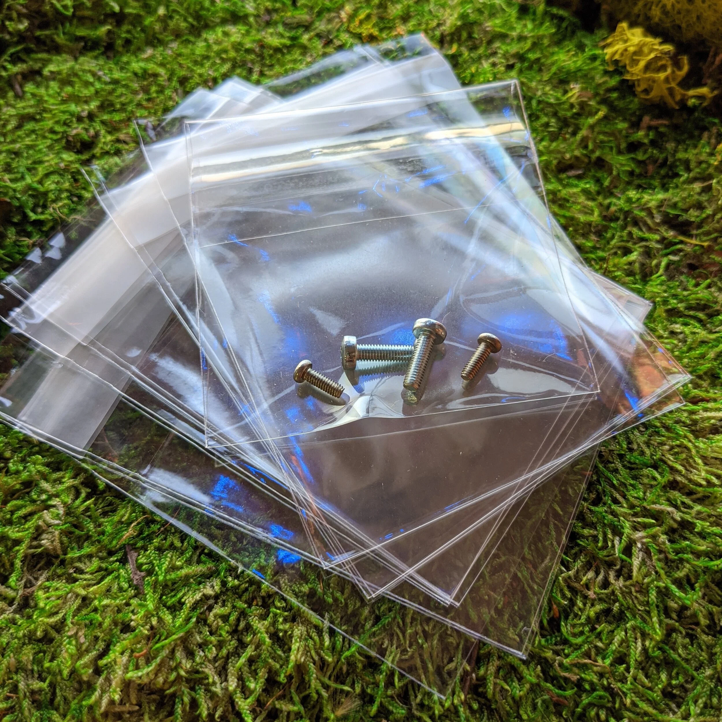
Compostable packaging
In an effort to be as environmentally friendly as possible we recently converted from traditional bubble wrap to a compostable paper packing material and got some cute little compostable baggies for screws too. Modules will still come in the pink bubble wrap baggie for ESD protection until we find a more eco-friendly way to protect circuitry. We're doing our best 🌍💚♻️
November purchases support AFRORACK!
Buy for yourself
or
Buy for a student!

During the month of November 20% of proceeds will be donated to AFRORACK.
Don’t have a modular setup but want to support? Purchase an item from our web store, add the word “GIFT” in the memo box when ordering, and the item you purchase will be shipped directly to AFRORACK in support of their student workstations.
"Does stink die in space?"
… or just another demo segment from SynthBooth streaming.
In this segment Wes shows how much fun two LFOs, one Sum&Slew mixer, and one LP-VCF can be. Just those three inspire a contemplation on laundry in space.
SynthBooth thanks
SynthBooth was so much fun! Thanks to everyone who tuned into our live stream from the synth “patch” 🎃. We got to virtually meet some great people and now have many hours of bleeps and ramblings available on youtube.
Also thanks to Anna for setting it up and to all the panelists and performers that made the event so entertaining and inspiring.
Also grateful for this write-up by the folks at gearnews.com! 🙏
https://www.gearnews.com/synthbooth-stem-modular-connecting-modular-with-science-math-and-engineering/
Strange times that we live in but it is so encouraging to see everyone come together virtually.
💜🎛️🗽
20% donated through the end of 2020!!

Pleased to announce that throughout the rest if this year we will be donating 20% of our proceeds to organizations that are working to bring music technology and opportunities to communities that are underrepresented in the industry.
With all that has happened this year our focus has shifted somewhat. First off the pandemic got us thinking less about in-person events and more about module production. Second, with inequality still on the forefront of our minds, and our limited ability to do much community outreach of our own, we wanted to find ways to support organizations that are continuing to do the work.
With new products in the pipeline this seemed like a good time to give back in this way. The organization will change each month, and this month we will be donating to @williemaerockcamp! They have been an incredible part of the NYC community for years and their new Future Sounds program is a huge inspiration! Check them out if you don't already know.
It's been a rough year but we will continue to spread love (it's the Brooklyn way).
💜🎛️🗽
Introducing the LP-VCF and Sum&Slew!
We are excited to reveal two new modules! Our 6hp low pass filter and Sum&Slew 4 channel mixer are here! We’ll be posting demos all weekend through SYNTHBOOTH and on our Twitch channel, as well as FB and IG. The controls and jacks are laid out with the intention of making them intuitive to use and for the signal flow to be easy to see.
LP-VCF is a four pole low pass filter. It’s a great companion to our VCO that will be released later this year, and can also self oscillate. A great analog filter and also very fun to use as a sound source.

Sum&Slew is a 4 channel mixer that provides option to glide between output voltage levels. This was initially thought of as a way to create a stepped sequence from a series of gates, but is basically a DC coupled mixer. Plug multiple outputs from our LFO into this and create unique modulating waveforms.

October Synthing returns!!
Back from the dead! Or at least back again. The collection of tracks made largely with STEM Modular modules last October is now available on Bandcamp. Not that you HAVE to make spooky sounds with these modules, but really why wouldn’t you?

SYNTHBOOTH
We are very excited to be exhibiting at SYNTHBOOTH next weekend (Oct 16-18)! There will be some new modules to show off as well as pre-sale for said modules (which will be shipping late-November). Get your tickets if you haven’t already. We’ll also be streaming through the weekend on Twitch so drop in and say hi to us over there too!
